The latest reviewed version was checked on 29 March 2013. There are template/file changes awaiting review.


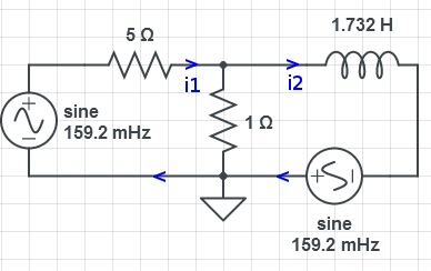
The series components can be lumped together .. which simplifies the circuit a bit.
Node Analysis


Mesh Analysis


Solving

Which is the same as the voltage through the 1 ohm resistor.
Thevenin voltage

Make ground the negative side of 


Solving

Norton Current

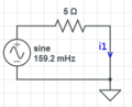


Thevenin/Norton Impedance

short voltage sources, open current sources, remove load and find impedance where the load was attached

check

yes! they match
Evaluate Thevenin Equivalent Circuit

Going to find current through the resistor and compare with mesh current

yes! they match
Find Load value for maximum power transfer

Find average power transfer with Load that maximizes


Simulation

The circuit was simulated. A way was found to enter equations into the voltage supply parameters which improves accuracy:


To compare with the results above, need to translate the current and voltage through the resistor into the time domain.
Period
Period looks right about 6 seconds ... should be:

Current
Current through 1 ohm resistor, once moved into the time domain (from the above numbers) is:

From the mesh analysis, the current's through both sources were computed:

The magnitudes are accurate, they are almost π out of phase which is can be seen on the simulation.
Voltage
The voltage is the same as the current through a 1 ohm resistor:

The voltage of the first (left) source is:

The magnitudes match. The voltage through the source peaks before the current because the first source sees the inductor.
The voltage through the resistor should peak about 171 - 45 = 126° before the source ... which it appears to do.
| This article uses material from the Wikipedia article Metasyntactic variable, which is released under the Creative Commons Attribution-ShareAlike 3.0 Unported License. |